
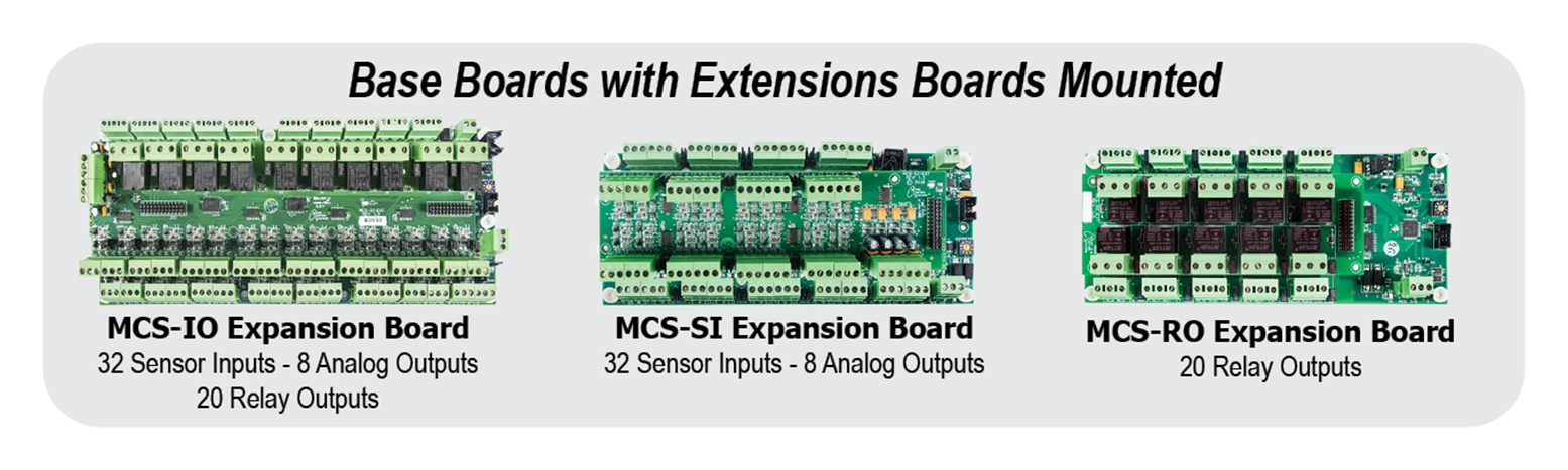
Controls Expansion Boards
MCS Expansion Boards are for use with an MCS-MAGNUM, MCS-8, or MicroMag with version 18 firmware.
| Voltage | UL Recognized? | ROHS Compliant? | # of Sensors | # of Relays | # of Analog Outputs |
|---|---|---|---|---|---|
| 12VDC | Yes | Yes | 16 | 10 | 4 |
| Part Number |
MCS-IO-BASE/-EXT |
|---|---|
| Description |
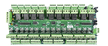
MCS-IO-BASE has sixteen 0-5vdc sensors inputs, ten 230vac 5amp relays outputs, and four 0-10vdc analog outputs that can be expanded to thirty-two 0-5vdc sensors inputs, twenty 230vac 5amp relays outputs, and eight 0-10vdc analog outputs by pairing with the -EXT Board within the footprint of the -BASE board. |
| Spec Sheets | |
| Installed Sheets |
Installed MCS-IO-EXT to MCS-IO-BASE
Instructions 
|
| Wiring Diagrams |
MCS-IO-BASE/-EXT
|
| Dimensional Drawings |
MCS-IO-BASE/-EXT 3D
|
| Part Number |
MCS-SI-BASE/-EXT |
|---|---|
| Description |
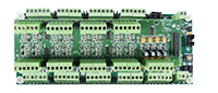
MCS-SI-BASE has sixteen 0-5vdc sensors inputs, and four 0-10vdc analog outputs that can be expanded to thirty-two 0-5vdc sensors inputs, and eight 0-10vdc analog outputs by pairing with the -EXT Board within the footprint of the -BASE board. |
| Spec Sheets | |
| Installed Sheets | |
| Wiring Diagrams | |
| Dimensional Drawings |
MCS-SI-BASE/-EXT 3D
|
| Documents |
Setting Address for Expansion
Boards
|
| Part Number |
MCS-RO-BASE/-EXT |
|---|---|
| Description |
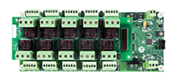
MCS-RO-BASE has ten 230vac 5amp relays outputs that can be expanded to twenty 230vac 5amp relays outputs by pairing with the -EXT Board within the footprint of the -BASE board. |
| Spec Sheets | |
| Installed Sheets |
Installed MCS-RO-EXT to MCS-RO-BASE
Instructions |
| Wiring Diagrams |
MCS-RO-BASE/-EXT
|
| Dimensional Drawings |
MCS-RO-BASE/-EXT 3D
|
| Documents |
Setting Address for Expansion
Boards
|
| Part Number |
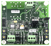
MCS-MODBUS-IO-12 |
|---|---|
| Description |
MCS-MODBUS-IO-12, mounts with four #6 sheet metal screws through nylon collars at corners of board. The MCS-MODBUS-IO-12 gives the MCS-MAGNUM-12 the ability to act as a Modbus Master using the Modbus RTU Protocol. This allows the MCS-MAGNUM-12 to communicate to Modbus slave devices (such as Variable Frequency Drives, Compressors, etc.) to send and access parameters. The MCS-MODBUS-IO-12 performs like an MCS-RO-BASE and MCS-SI-BASE to the MCS-MAGNUM-12. This allows the MCS-MAGNUM-12 to control 10 relays, 4 analog outputs and read 16 sensors inputs. Multiple MCS-MODBUS-IO-12 boards may be connected to the MCS-MAGNUM-12 following the MCS-I/O standards. |
| Spec Sheets |
MCS-MODBUS-I/O-12 Spec
Sheet
|
| Wiring Diagrams | |
| Documents |
MCS-MODBUS-I/O Manual
|
| Dimensional Drawings |
MCS-MODBUS-IO-12 3D
|
| Firmware |
MCS-MODBUS-I/O
Firmware Version 3.01I (Size: 40 KB) MCS-MODBUS-I/O IMPORTANT
UPDATE MCS-MODBUS-I/O IMPORTANT
UPDATE |